AutoAssembler Automates Change Analysis for Complex CAD Assemblies in Minutes

Sai Nelaturi

Adam Sage

Ganesh Subramanian
August 25, 2026 • 4 min read
Ask a manufacturing engineer how they determine what changed between two product revisions, and most describe the same routine: open both CAD files, place the windows side by side, and rotate the models in lockstep. They isolate parts, hide larger components, take section cuts, and squint. On a large assembly, this can consume hours. The changes that matter most—a fastener swapped inside a housing, a bracket moved a few millimeters, or a wall made slightly thicker—are often the hardest to see.
That comparison is not a formality. It determines how much of an existing manufacturing process plan can be reused and how much must be rebuilt. On assemblies with about 1,000 parts, AutoAssembler can complete the analysis in roughly one to two minutes. Manual comparison takes hours, and the effort grows nonlinearly as assemblies get larger.
Software engineers solved a version of this problem long ago. Every code change is reviewed as a "diff": a precise account of what changed between one version and the next. Nobody re-reviews the entire codebase. Build systems go further: an incremental compiler rebuilds only the affected modules and reuses everything else. A manufacturing process plan is, in effect, compiled from a design. When the design changes, only the affected parts of the plan should need to be rebuilt. AutoAssembler makes that approach practical for physical products.
Reuse Is the Whole Point
When a product is revised or configured for another market, option package, or variant, most of it stays the same. The factory already knows how to build those parts. Process plans are tuned to specific stations, tooling and fixtures have been validated, and work instructions capture years of plant experience. None of that needs to be recreated for unchanged parts. The challenge is identifying those parts quickly and confidently.
This product update or variant scenario is the norm, not the exception: products evolve, configurations multiply, and running changes arrive continually. A reliable diff tells planners which stations are affected, which plans transfer directly, and where engineering effort is required. An engineering change order becomes a scoped, reviewable update instead of a reason to start over.
Why Engineering Change Analysis Is Hard
Comparing two documents is straightforward because text is orderly: lines appear in sequence, and characters either match or they do not. Physical designs offer no such structure, and the difficulties begin before a meaningful comparison can be made.
The input rarely arrives in a consistent form. A design may come directly from CAD with exact geometry, through a PLM export that obscures the underlying geometry, or only as a mesh—a tessellated approximation that has discarded much of the original design information. A practical system must work with exact geometry and meshes while reconciling differences among tools, formats, and tolerances.
Then there is noise. Export the same unchanged part twice and the resulting files may still differ: a surface is approximated differently across formats, or a part's position drifts by a fraction of a millimeter when mating relationships are recalculated. A naive comparison flags a change where none exists. Separating genuine engineering changes from this digital static—reliably and across incompatible formats—is a central technical challenge, and the part that is invisible when it works.
Anatomy of Design Changes
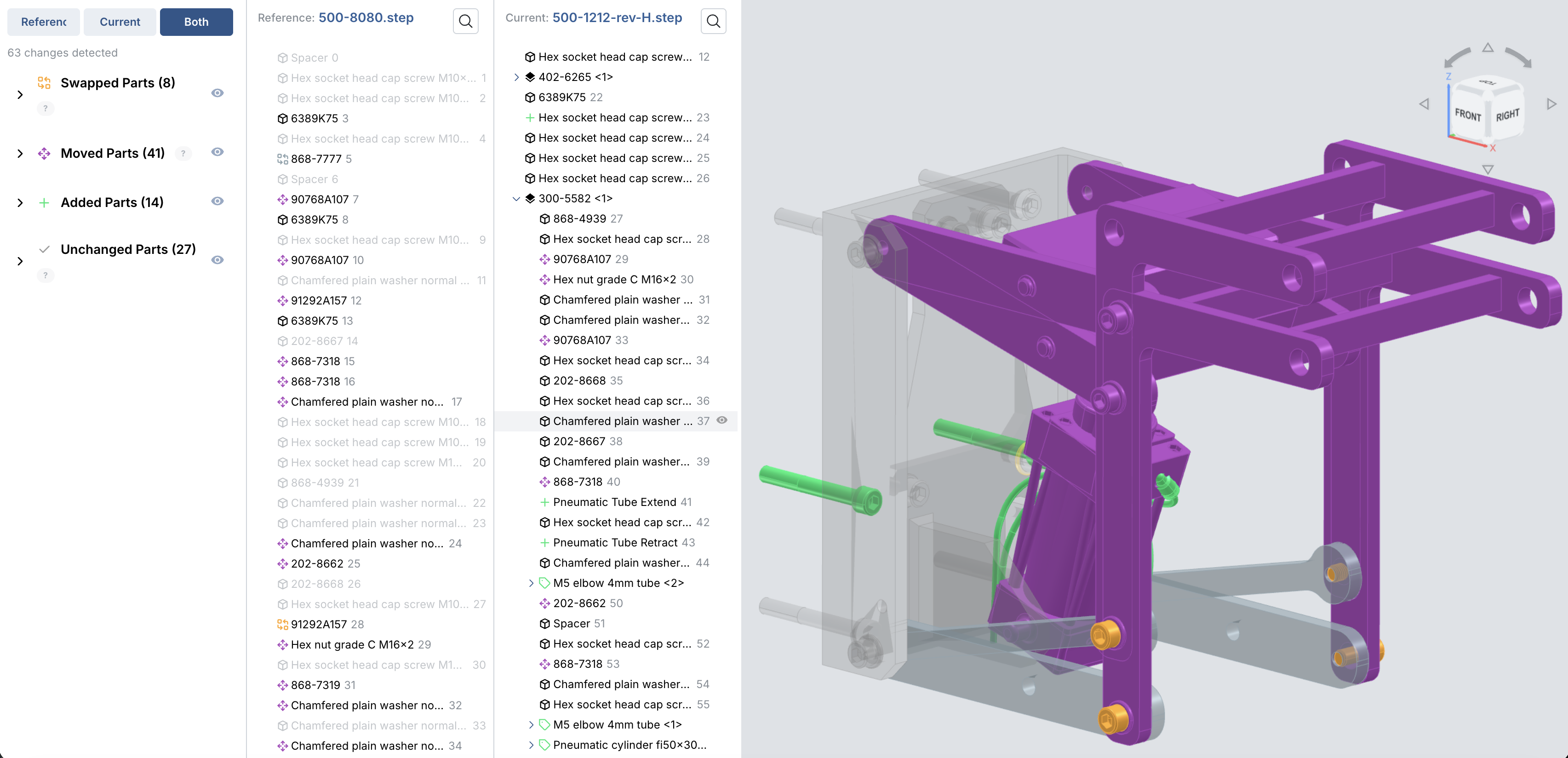
Once the system can trust that a difference is genuine, a simple yes-or-no answer is not enough. As Figure 1 shows, design changes fall into four event types—additions, removals, moves, and swaps—each with different implications for a manufacturing planner.
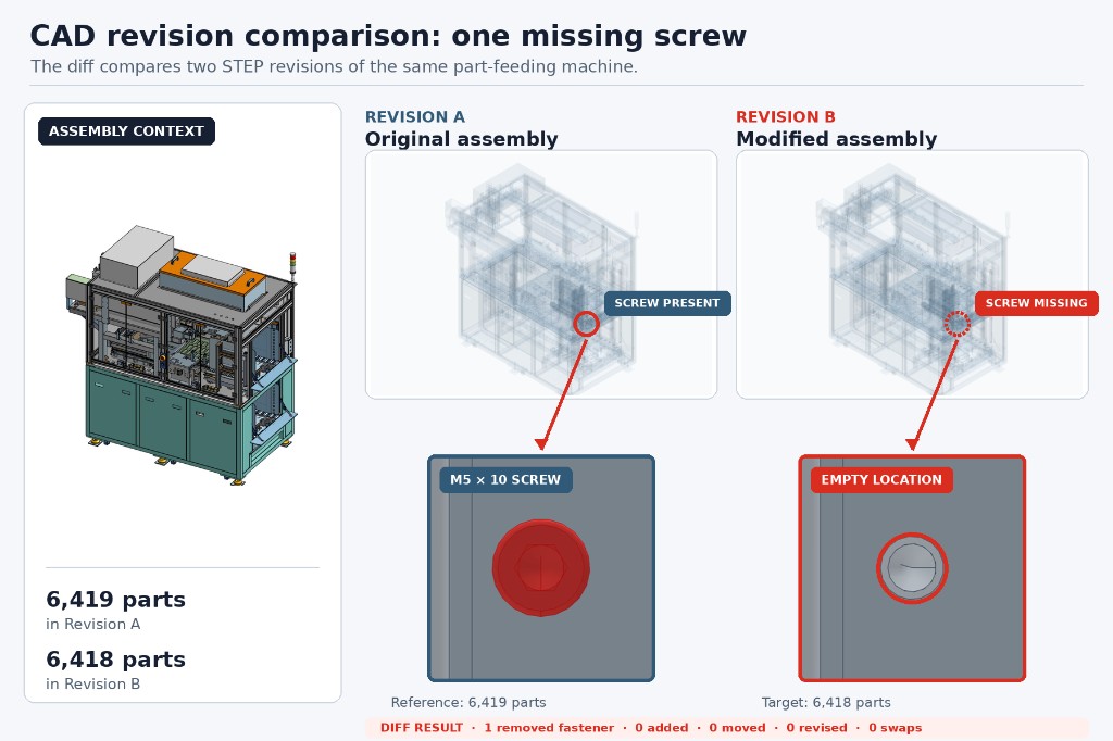
Additions and removals are the clearest: a part appears in one version and not the other. They become useful only after the system can separate them from moves and swaps, which depend on assembly context. As Figure 3 shows, drift between design revisions can lead to serious manufacturing issues, such as a missing bolt.
Moves are repositioned parts, but a moved part is not always a design change. Mechanisms articulate: a linkage folds, a door swings, or a piston sits at a different point in its travel. The same design may therefore be captured in a different state. Mistaking articulation for a revision buries planners in false changes.
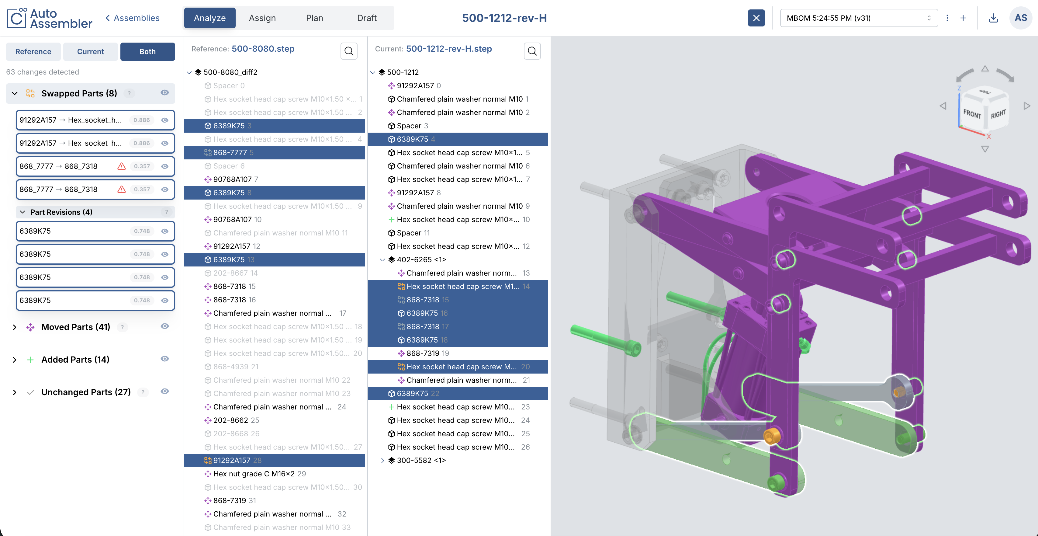
Swaps are often the most valuable and the most difficult: one component replaces another in the same functional role. A bolt of one length gives way to another, a connector is superseded, or several parts are replaced at once. Comparisons across geometry alone makes these look like unrelated additions and removals. Assembly context—the parts' positions, neighbors, and relationships—reveals that they occupy the same role. That becomes harder when identical hardware appears throughout a machine.
Swaps matter because design changes and process changes are not always the same. Replacing a longer bolt with a shorter one is a real design change, but the assembly step may remain nearly identical: the same station, motion, and sequence, perhaps with a tool or torque adjustment. Correctly identifying the swap lets the planner modify an existing step instead of writing a new one. Across thousands of parts, that turns potential rework into a targeted process adjustment.
Reading Intent From Model Revisions
A CAD model is a static snapshot of geometry. It does not say that one bolt serves the same role as another, that a part stayed put while the mechanism around it moved, or that several small components replaced one larger component. Engineers normally reconstruct that intent by hand, one revision at a time.
AutoAssembler is built on C-Infinity's Assembly Intelligence: a computational form of mechanical intuition that lets it examine a static 3D assembly and infer how its parts fit together, interact, and can move. It combines a geometry-and-assembly perception layer with a change-analysis layer. Using geometry, position, and surrounding components as context, it classifies part-level differences as additions, removals, moves, or swaps while filtering out export noise.
Confidence matters as much as speed. AutoAssembler reports confidence and flags ambiguous matches so engineers can focus review on the uncertain cases.
From PLM Change Records to Manufacturing Action
Product lifecycle management (PLM) systems are foundational to configuration and change management. They record revisions, approvals, affected items, and product configurations, providing both a snapshot of each design state and the authoritative system of record for an Engineering Change Order (ECO). What they do not provide is a detailed analysis of how the assembly itself changed or what those changes mean for manufacturing.
AutoAssembler complements PLM by performing that analysis. It compares the reference and current designs, identifies additions, removals, moves, and swaps, and shows which existing manufacturing plans can be reused and which require attention. That makes AutoAssembler a natural next step immediately after an ECO is filed: PLM records and governs the change, while AutoAssembler determines its physical and manufacturing impact.
A pull request tells a reviewer what changed. An incremental compiler does more: it reuses the prior build and rebuilds only what changed. That is the real prize for manufacturing—a process plan that can be recompiled from its predecessor instead of written again.